Description
Detailed Specifications
- Optical interface: Dual fiber ports, multi-mode fiber for standard version. Fiber communication provides complete galvanic isolation, immune to ground loop and heavy electromagnetic interference in industrial field. Maximum transmission distance reaches 12km, supporting long-distance distributed I/O layout.
- Data transmission: Fixed communication rate dedicated for Tricon TriBus remote extension. It transmits I/O sampling data, voting results and diagnostic alarms between main chassis and remote I/O racks. Fiber link fault detection is built in, automatically reporting communication loss to CPU.
- Redundancy & self-test: Three internal processing legs run synchronously. 2oo3 voting logic works consistently with main rack TMR architecture. Continuous background diagnostics monitor optical signal power, link status and internal circuit health. Any single leg fault will not break the remote I/O operation.
- Internal bus: Interacts with main processor and remote I/O modules through proprietary TriBus. Time synchronization is maintained between main rack and remote rack to guarantee consistent safety logic scan and voting.
- Power requirement: Powered by rack backplane 20–32VDC supply. Integrated reverse polarity and overvoltage protection circuits. Hot-swap maintenance is supported for racks with redundant spare slots.
- Environmental specs: Operating temperature -40℃ ~ +70℃; storage temperature -40℃ ~ +85℃; relative humidity 5%–95% non-condensing. Conformal coated variant is available for cabinets with dust, moisture and mild corrosive vapor.
- Spare installation note: After module replacement, firmware revision must match the existing Tricon system. Version mismatch will trigger fiber link handshake failure, intermittent communication dropout or leg synchronization error. This module is only compatible with classic Tricon platform, cannot work on Tricon CX system.
Physical Characteristics
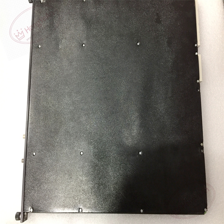
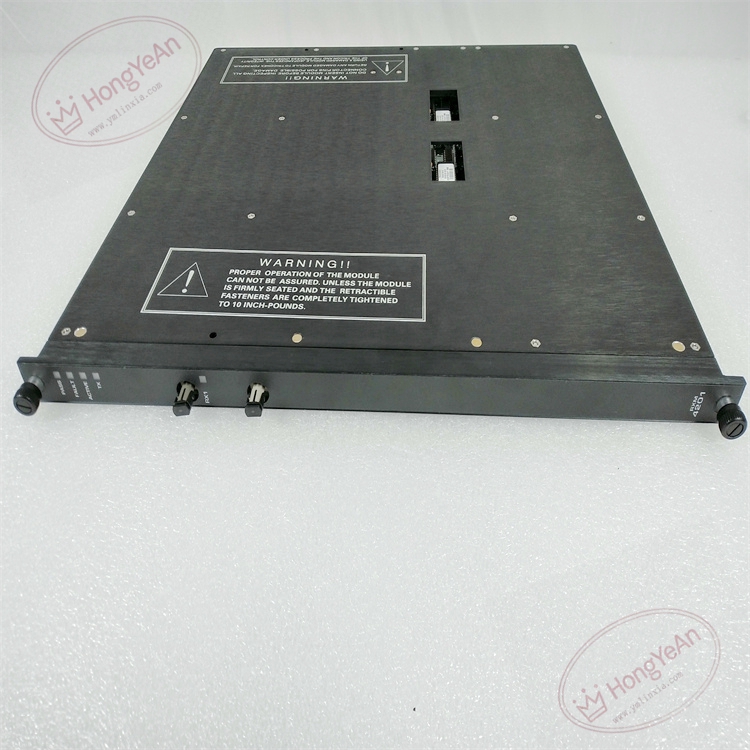
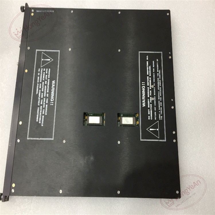
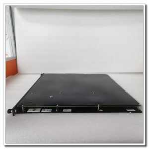
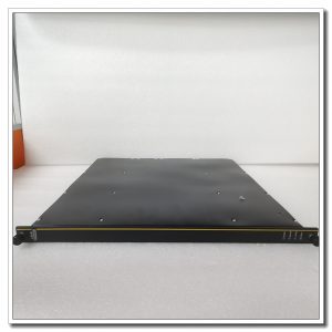
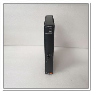
Rack plug-in fiber extension board. Front panel fitted with LED indicators showing module PASS/FAULT, triple leg synchronization, optical link status and optical signal strength. Fiber connectors locate on front panel for field fiber wiring. Gold finger contacts on rear connect to rack backplane for power supply and TriBus data exchange. No field I/O wiring terminals on the module. Model marking is printed on metal housing, mechanical keying prevents wrong-slot installation.
Site Application Scenarios
This remote fiber extension module is widely adopted in petrochemical plants, refineries, natural gas compressor stations, thermal power plants and offshore platforms. It is used in ESD emergency shutdown, fire & gas detection and turbomachinery protection systems. When field instrument room is far away from main SIS control cabinet, 4201 allows placing I/O sub-rack near field transmitters and solenoid valves, shortening copper signal cables and reducing noise interference. Fiber isolation also solves ground potential difference problems between separated building cabinets.
Maintenance Reminder: Safety-critical communication extension hardware. Complete module failure will cut off all remote I/O signals, and related safety loops will execute predefined safe state strategy. Technicians need to regularly check optical power value and fiber cable integrity in routine maintenance.
Operation & Maintenance Suggestions
- Anti-static wristband must be worn during module handling. Hot-swap replacement can be performed on racks configured with redundant slots. Disconnect fiber connectors gently; excessive bending or pulling will damage fiber core.
- Use qualified industrial multi-mode fiber cables. Keep fiber routes separated from high-power power cables. Maintain proper bending radius for fiber, avoid sharp corners or heavy extrusion. Clean fiber end faces before plugging in, dirty end faces cause signal attenuation and unstable link.
- Insert the module fully into rack slot to guarantee stable gold finger contact. After installation, configure remote rack parameters and run fiber link test. Verify all remote I/O data is correctly transmitted to main CPU, check system logs for leg mismatch and optical link alarms.
- Keep complete backup copies of project configuration and firmware files. Never disassemble faulty module on site; replace the whole unit directly once permanent hardware damage occurs.
Field Troubleshooting Reference
- Optical link fault alarm: Inspect fiber cable breakage, fiber end face contamination, fiber bending damage, and check optical power level.
- Remote I/O data intermittent loss: Check fiber connector tightness, cabinet temperature, and backplane gold finger dust/oxidation.
- System raises leg mismatch alerts: Confirm firmware consistency of three legs, clean dust and oxidation on backplane gold finger contacts.
- No LED illumination on front panel: Verify rack backplane power supply and confirm module is fully seated in slot.
- Remote rack cannot synchronize with main CPU: Check remote rack address configuration and TriBus parameter setting.
Reviews
There are no reviews yet.