Description
Detailed Specifications
- Optical interface: Dual fiber ports for redundant communication link. Multi-mode fiber is standard, supporting point-to-point connection between main chassis and remote I/O racks. Optical isolation eliminates ground potential difference and suppresses heavy electromagnetic interference in industrial environments.
- Transmission mechanism: Transmits TriBus data including I/O samples, voting results and diagnostic events between racks. Built-in real-time link monitoring detects fiber attenuation, connector contamination or cable break immediately and generates system alarms.
- Redundancy & self-test: Three independent processing legs run synchronously. 2oo3 voting ensures the module still works even one leg fails. Background self-test runs continuously without interrupting safety program execution.
- Internal bus: Communicates with Tricon CPU and local I/O modules through proprietary TriBus. Strict time synchronization keeps scanning cycle consistent across distributed racks.
- Power supply: Powered by rack backplane 20–32VDC. It has reverse polarity and overvoltage protection circuits. Hot-swap replacement is supported for racks with redundant slots.
- Environmental performance: Operating temperature range -40℃ ~ +70℃, storage temperature -40℃ ~ +85℃, relative humidity 5%–95% non-condensing. Conformal coated version is available for cabinets with dust, moisture and mild corrosive gas.
- Installation reminder: The firmware version of replacement module must match the existing Tricon system. Mismatch will cause handshake failure, intermittent communication dropout or leg synchronization error. It only fits classic Tricon racks and cannot be used on Tricon CX platform.
Hardware Features
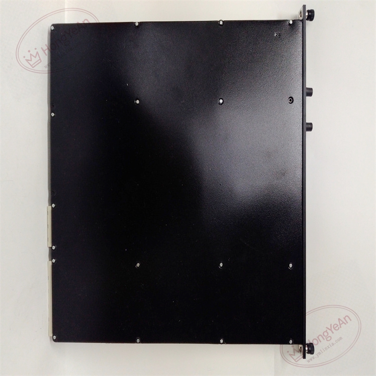
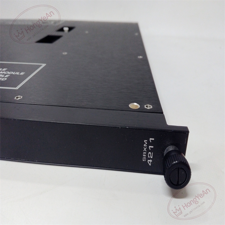
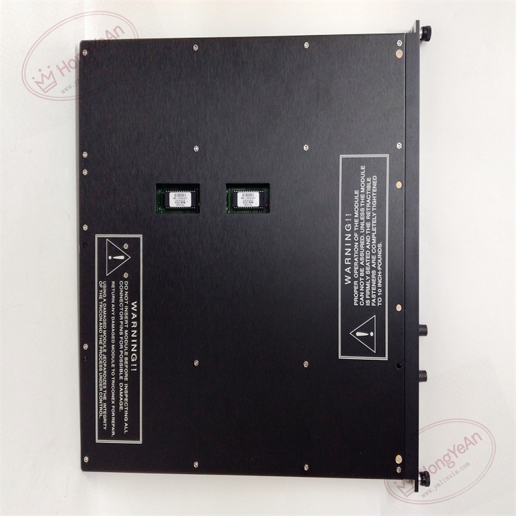
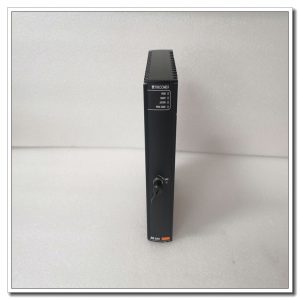
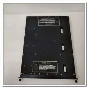
This is a rack plug-in board. The front panel is equipped with multiple LED lights, used to display module running state, three-leg synchronization status and optical link signal quality. Optical fiber connectors are placed on the front panel for easy field wiring maintenance. The rear gold finger contacts connect to the rack backplane to obtain power and TriBus signals. There is no field I/O terminal on the module body. The model number is printed on the side of the metal housing, and the mechanical key prevents wrong slot installation.
Application Scenarios
This fiber communication expansion module is commonly used in ESD emergency shutdown, burner management and turbomachinery protection systems for petrochemical plants, refineries, natural gas compressor stations, thermal power plants and offshore platforms. When field instrument points are scattered far from the main control cabinet, remote I/O racks with 4211 can be deployed near the site, shortening copper signal cables and reducing noise interference. Redundant fiber links improve the reliability of long-distance signal transmission.
Maintenance Tip: This is safety-related communication hardware. If the whole module fails, remote rack I/O signals will be disconnected, and the corresponding safety loops will enter pre-defined safe state. Daily maintenance needs to check optical power and fiber connection status regularly.
Maintenance & Operation Guidelines
- Wear anti-static wristband all the time when touching the module. Hot-swap maintenance can be done on racks with redundant slots. When plugging and unplugging fiber connectors, handle gently, avoid excessive bending and pulling the optical fiber.
- Use industrial qualified multi-mode fiber. Separate fiber routing from high-power cables of motors and inverters. Keep fiber bending radius within the specified range. Clean the fiber end face before installation; dirt will lead to signal attenuation.
- Push the module fully into the slot to ensure reliable contact of gold fingers. After installation, configure remote rack address and carry out fiber link test. Confirm all remote I/O data can be uploaded normally, and check system logs for leg mismatch and bus alarms.
- Keep backup of project configuration and firmware files. Do not disassemble the faulty module on site; replace the whole module when permanent hardware damage occurs.
Common Troubleshooting
- Optical link alarm: Check fiber breakage, end face contamination, excessive bending, and test optical power value.
- Intermittent loss of remote I/O data: Check connector tightness, cabinet temperature, dust and oxidation on backplane gold fingers.
- Leg mismatch warning: Ensure three legs use consistent firmware, clean the gold finger contacts.
- No LED light on front panel: Verify backplane power supply and confirm module is fully inserted.
- Remote rack fails to synchronize with main CPU: Check rack address setting and TriBus parameter configuration.
-300x300.jpg)
Reviews
There are no reviews yet.