Description
Detailed Specifications
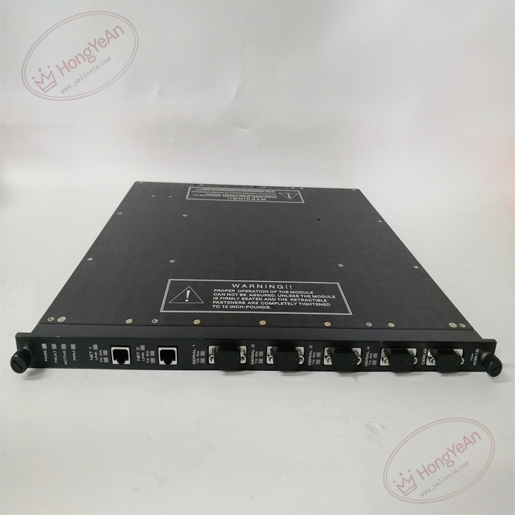
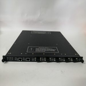
- Interface configuration: 2 × 10/100Base-T RJ45 Ethernet ports; 4 × configurable serial DB9 ports. Every communication port provides 500VDC galvanic isolation to cut ground loop interference between different automation subsystems.
- Protocol support: TCP/IP, Modbus TCP, Modbus RTU/ASCII, TriStation, SNTP time synchronization, TSAA multicast, UDP peer-to-peer communication, Trimble GPS time input. Serial port can be individually set as Modbus master or slave.
- Communication performance: Single serial port maximum baud rate reaches 115.2 kbps. The aggregated bandwidth of four serial ports is 460.8 kbps. Dual Ethernet ports support redundant network layout to improve link reliability.
- Redundancy & self-test: Three independent processing legs run synchronously following TMR design. 2oo3 voting ensures stable data forwarding even one leg fails. Continuous background diagnostics monitor port status, frame error count and link breakage, pushing alarm messages to system log.
- Internal bus: Interacts with Tricon CPU and I/O modules through proprietary TriBus. It transfers process variables, alarm events and configuration data. The communication module fault will not affect the safety trip logic execution of the SIS controller.
- Power requirement: Powered by rack backplane 20–32VDC supply, built-in reverse polarity and overvoltage protection. Hot-swap online replacement is supported for racks with redundant slots.
- Environmental specs: Operating temperature -40℃ ~ +70℃; storage temperature -40℃ ~ +85℃; relative humidity 5%–95% non-condensing. Conformal coated version is available for cabinets with dust, moisture and mild corrosive vapor.
- Installation reminder: This module requires Tricon system firmware v10.0 or higher. After replacement, firmware revision must match the existing system. Version mismatch causes network handshake failure, garbled serial data or leg synchronization error. It cannot be used on Tricon CX platform.
Hardware Features
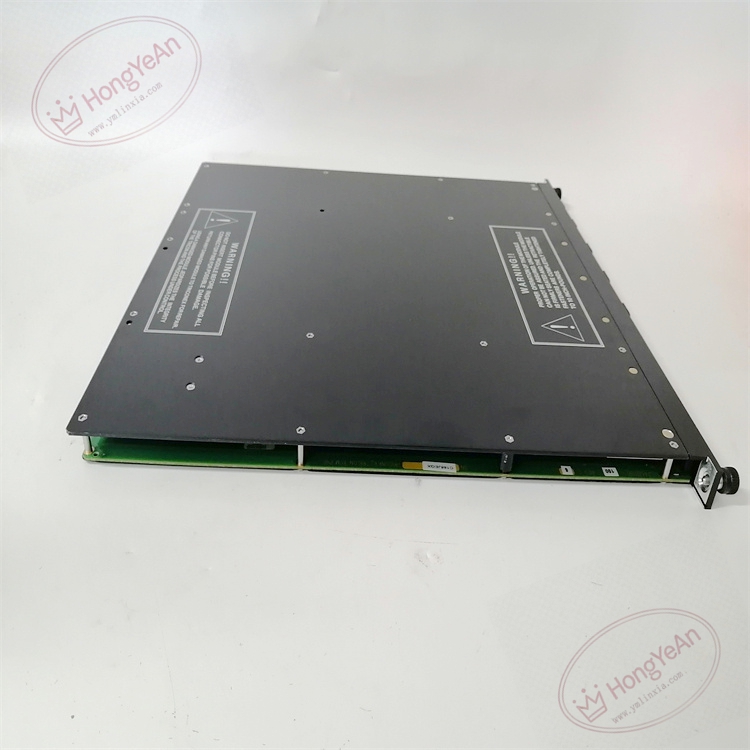
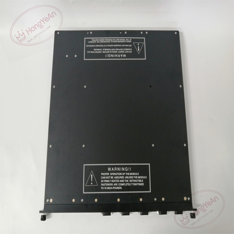
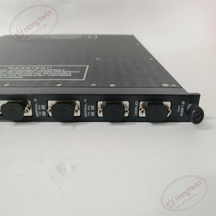
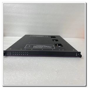
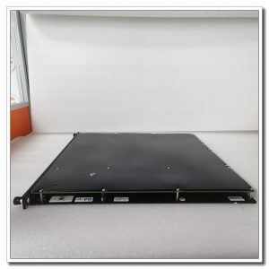
This is rack plug-in communication board. The front panel is fitted with LED indicators showing module PASS/FAULT, triple leg synchronization, Ethernet link status and serial port TX/RX activity. RJ45 and DB9 connectors are mounted on front panel for convenient field wiring maintenance. The rear gold finger contacts connect with rack backplane for power and TriBus data exchange. There are no field I/O terminals on the module body. Model marking is printed on metal housing, and mechanical keying prevents misinstallation into incompatible slots.
Application Scenarios
This multi-functional communication gateway is widely deployed in ESD emergency shutdown, burner management, turbomachinery protection and fire & gas detection systems for petrochemical plants, refineries, natural gas compressor stations, thermal power plants and offshore platforms. It acts as the bridge between Tricon SIS and DCS, engineering workstation, HMI and Modbus instruments. Dual Ethernet design supports redundant network to reduce single point failure risk. Serial ports can connect to legacy Modbus RTU devices, realizing seamless integration of old and new automation systems.
Maintenance Tip: This is safety-related communication hardware. Module failure cuts off external data exchange, while core safety interlock logic still runs normally. Daily maintenance should check network error counters, cable integrity and port diagnostic alarms.
Maintenance & Operation Guidelines
- Anti-static wristband must be worn when handling the module. Hot-swap replacement can be performed without shutting down the rack. Disconnect all external network and serial cables before removing the card to avoid static damage.
- Use shielded twisted pair cables for serial and Ethernet wiring. Separate communication cables physically from high-power cables of motors and inverters to reduce electromagnetic interference. For RS485 bus, install terminal resistors at both ends of the trunk line.
- Insert the module fully into rack slot to guarantee stable gold finger contact. After installation, configure IP address, serial port baud rate, parity and master/slave mode. Carry out point-to-point communication test, verify read/write of Modbus registers is normal, then check system logs for leg mismatch and TriBus alarms.
- Keep complete backup copies of project configuration and firmware files. Never disassemble faulty module on site; replace the whole unit directly once permanent hardware damage occurs.
Common Troubleshooting
- Ethernet link down alarm: Check RJ45 cable, verify IP address consistency, inspect switch port status and cable damage.
- Serial communication intermittent dropout: Check DB9 terminal tightness, shielding grounding, bus terminal resistor and baud rate matching.
- System raises leg mismatch warnings: Confirm firmware consistency of three legs, clean dust and oxidation on backplane gold finger contacts.
- No LED illumination on front panel: Verify backplane power supply and confirm module is fully seated in slot.
- Modbus data reading abnormal: Check register alias mapping, byte order setting and noise interference on communication lines.
Reviews
There are no reviews yet.