Description
Detailed Specifications
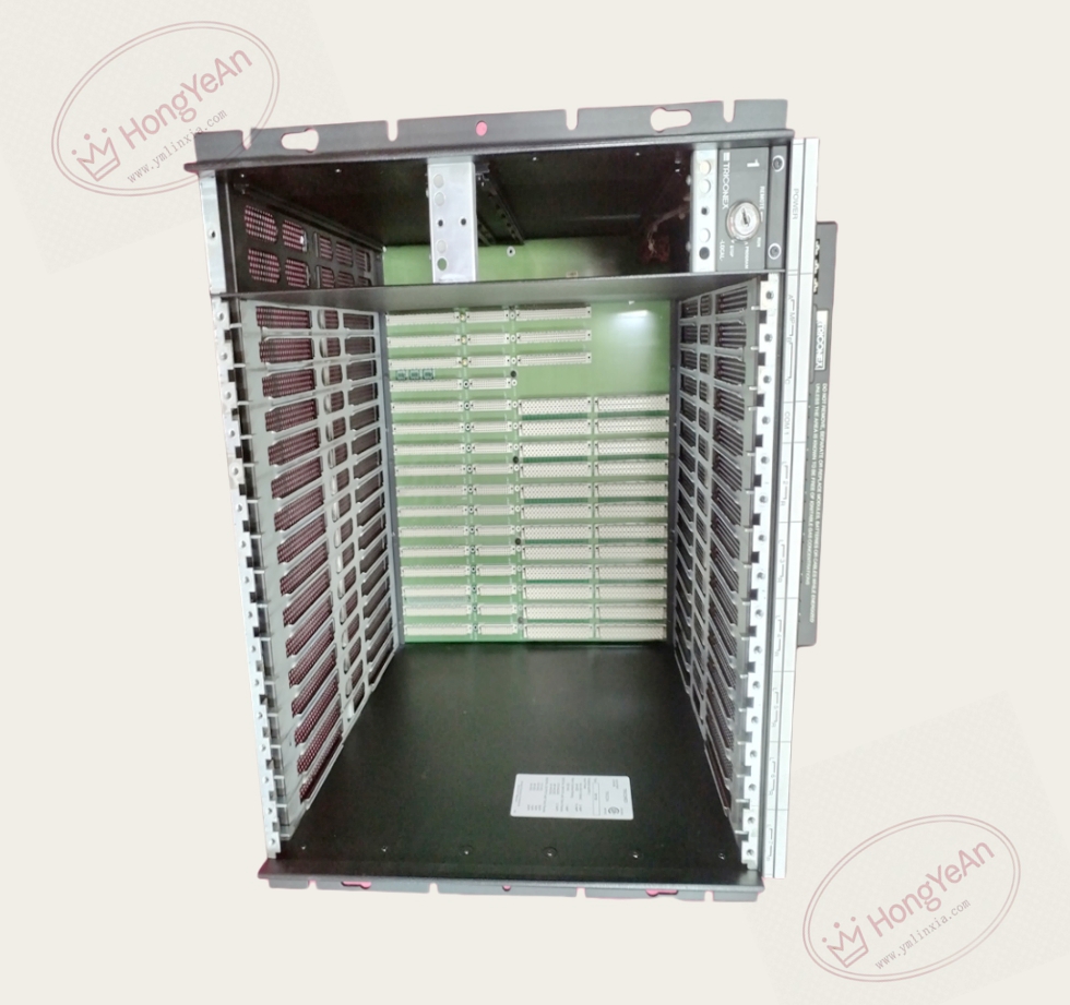
- Slot layout: This main chassis holds processor slots plus up to six pairs of I/O module slots. Each slot group supports triple modular redundant I/O cards. The built-in dedicated TriBus backplane completes high-speed data exchange among all installed modules.
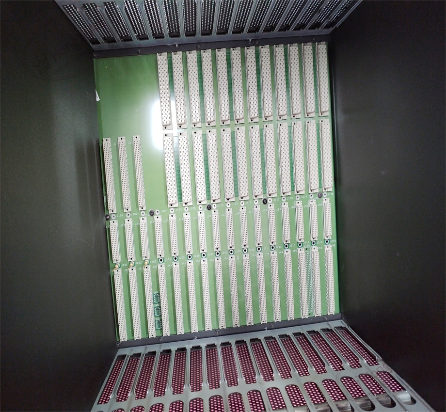
- Backplane characteristics: The internal backplane implements synchronized communication for three TMR legs. Gold finger connectors adopt offset mechanical anti-reversal design, and slot keying prevents wrong-type module insertion.
- System compatibility: Matches Tricon v9 and v10 classic SIS platform. Works with series of Tricon CPU, AI, DI, AO, DO and communication modules. It cannot be used with Tricon CX series systems.
- Power layout: The chassis reserves mounting positions for redundant power supply modules. The backplane distributes 20–32VDC power to each plug-in module. It has built-in filtering to restrain power disturbance inside the cabinet.
- Environmental specs: Operating temperature -40℃ ~ +70℃; storage temperature -40℃ ~ +85℃; relative humidity 5%–95% non-condensing. The metal housing has good mechanical vibration resistance, suitable for industrial cabinet installation.
- Installation reminder: The chassis itself is a passive mechanical and backplane assembly. After module installation, all module firmware versions need unified matching. Mismatched firmware will cause TriBus communication failure or leg synchronization alarm.
Hardware Features
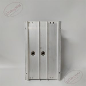
It is a metal cabinet frame with integrated backplane. The front is the module insertion opening, each slot has dedicated mechanical key. Internal wiring is fixed on the backplane, no external field signal terminals on chassis. Multiple ventilation openings are designed for heat dissipation of internal modules. The model number is marked on the side panel of the housing.
Application Scenarios
This high-density main chassis is the core rack of Tricon SIS. Widely applied in petrochemical plants, refineries, gas compressor stations, thermal power plants and offshore platforms, deployed for ESD emergency shutdown, burner management and turbomachinery protection systems. It carries all core safety controller hardware. The six groups of I/O slots can accommodate rich signal points for medium and large safety projects.
Maintenance Tip: This is safety-critical system carrier hardware. Backplane damage will lead to the failure of all modules installed inside the rack, and the SIS system will trigger pre-defined safe state. Daily maintenance should check ventilation status, dust accumulation and backplane gold finger condition.
Maintenance & Operation Guidelines
- Wear anti-static wristband before opening the cabinet or plugging modules. Avoid touching backplane gold fingers directly. Do not place metal debris inside the chassis.
- Keep cabinet ventilation unobstructed. Regularly clean dust inside the chassis, excessive dust will cause poor contact and intermittent communication faults. Avoid liquid or corrosive gas entering the cabinet.
- Install modules into the corresponding keyed slots. After inserting all hardware, check backplane power supply, download configuration and run full system test. Observe leg synchronization status and check TriBus diagnostic logs.
- Keep backup copies of project configuration and firmware files. If backplane is permanently damaged, replace the whole chassis assembly. Do not attempt to repair the backplane circuit on site.
Common Troubleshooting
- Multiple modules report PASS light off and fault alarm: Check rack power supply, inspect backplane for dust or oxidation.
- Leg mismatch warning of CPU: Check whether modules are inserted into the correct slots, clean backplane gold fingers, verify firmware consistency.
- TriBus communication error: Inspect module seating condition and backplane integrity.
- Module cannot be inserted smoothly: Check slot mechanical key, confirm module model matches the chassis.
- Overheating alarm: Check cabinet fan, air filter and chassis ventilation channel for blockage.
-300x300.jpg)
Reviews
There are no reviews yet.