Description
Detailed Specifications
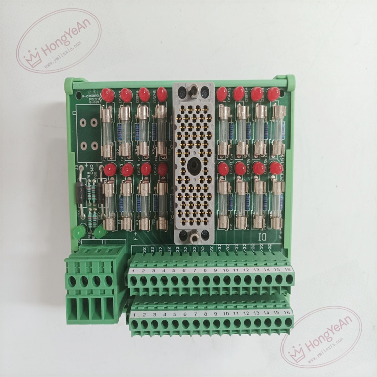
- Channel setup: 16 commoned digital input points per panel, rated for 24V AC/DC signal. Typical leakage current 2.5mA, max value 3.3mA.
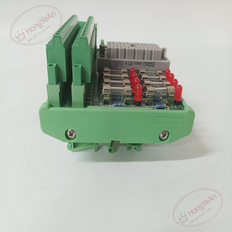
- Circuit protection: Each channel is fitted with 1A slow-blow fuse, equipped with blown-fuse indicator lamp to quickly locate damaged loop.
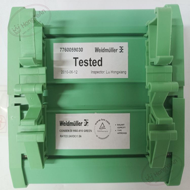
- Matching requirement: It works with 32-point DI modules like 3503E /3505E. One 32-point DI module requires two 9563-810 termination panels.
- Wiring structure: Shared common power terminals PWR+ / PWR-. Terminal blocks are convenient for field instrument wiring and inspection.
- Environmental specs: Operating temperature -40℃ ~ +70℃; storage temperature -40℃ ~ +85℃; relative humidity 5%–95% non-condensing. It can tolerate cabinet vibration and dust in industrial sites.
- Installation reminder: This is a passive termination board without backplane gold fingers. It is mounted inside control cabinet, separate from rack I/O slots. Designed for classic Tricon v9~v10 systems, not compatible with Tricon CX.
Hardware Features
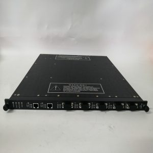
It is a cabinet-mounted terminal panel with terminal blocks and status indicator LEDs on front side. Each signal channel corresponds to independent fuse and fuse fault indicator. Pre-marked channel labels (1-16 or 17-32) are supplied for marking. Metal mounting bracket supports cabinet installation. Model number is printed on housing surface.
Application Scenarios
This digital input termination panel is widely used for ESD emergency shutdown, fire & gas detection, turbomachinery protection and burner management systems in petrochemical plants, refineries, gas compressor stations, thermal power plants and offshore platforms. It collects on-site discrete signals from pressure switches, level switches and temperature switches. Individual channel fuse prevents short-circuit on field cable from damaging the Tricon I/O module.
Maintenance Tip: This is safety-related signal wiring hardware. Short circuit on field wire will blow the corresponding channel fuse and trigger fuse alarm, while other signal points still work normally. Daily maintenance needs to check fuse status and terminal tightness.
Maintenance & Operation Guidelines
- Wear anti-static wristband during wiring work. Cut off field 24V signal power before modifying wiring to avoid surge current.
- Keep cabinet interior clean. Prevent dust accumulation on terminals, loose terminals will create intermittent signal failure. Avoid corrosive gas and liquid touching the terminal board.
- After wiring completion, check each channel’s fuse and indicator lamp. Perform point signal simulation test to confirm DI signal can be transmitted normally to Tricon I/O module. Check system diagnostic log for fuse failure alarms.
- Store spare slow-blow 1A fuses of the same specification. Replace blown fuse with matched rating, do not use oversized fuses.
Common Troubleshooting
- Fuse blown alarm: Inspect field cable short circuit or overload, check switch wiring insulation.
- No DI signal feedback: Check fuse integrity, terminal looseness, field sensor status and 24V loop power.
- Intermittent signal dropout: Check terminal oxidation, cabinet vibration and cable insulation aging.
- Multiple channels abnormal: Verify shared common power supply and common terminal connection.
- Fuse indicator not lighting after fuse blow: Check indicator circuit and wiring polarity.
-300x300.jpg)
Reviews
There are no reviews yet.