Description
Core Specifications
- Channel count: 16 commoned digital output channels, rated for 24VDC field loops.
- Circuit protection: Each channel fitted with fast acting fuse and LED blow indicator.
- Compatible I/O card: Matches Tricon 3624, 3625 supervised digital output modules.
- Cable connection: Connect to Tricon DO module via dedicated flat ribbon cable.
- Wire specification: Accepts 14AWG ~ 22AWG solid or stranded copper wires on screw terminals.
- Platform compatibility: Classic Tricon v9 ~ v11 system, not fit for Tricon CX.
- Mounting: DIN rail installation inside control cabinet. It is a passive panel without backplane gold fingers, cannot be inserted into rack slots.
- Environmental range: Operating temperature -40℃ ~ +70℃; storage temperature -40℃ ~ +85℃; humidity 5%–95% non-condensing.
- Installation reminder: Unused channels need load resistors installed, otherwise the system will trigger missing-load diagnostic alarm.
Physical Construction
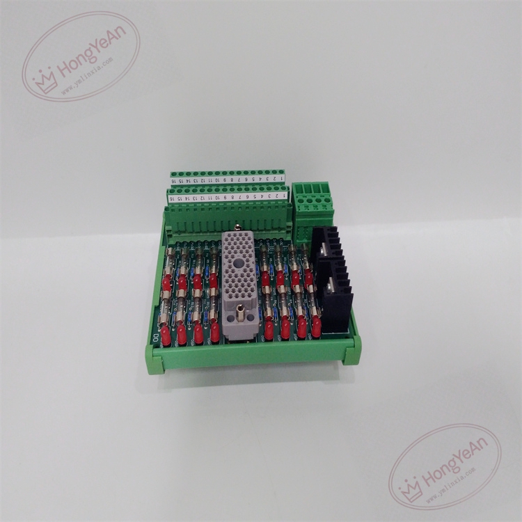
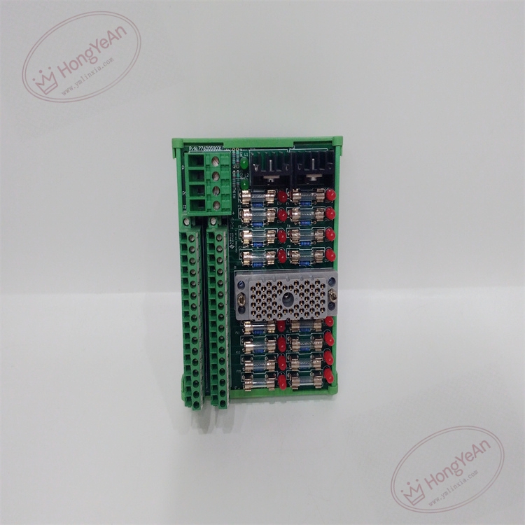
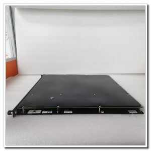
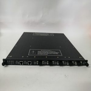
PCB assembly enclosed in green plastic housing. Front panel is equipped with screw terminal blocks for field wiring. Fuse holders and corresponding fault indicator LEDs are arranged channel by channel. One multi-pin connector is reserved for ribbon cable to link to Tricon DO module. Channel number marking is printed on the panel surface for easy site checking.
Application Areas
This termination panel is widely deployed in petrochemical plants, refineries, gas compressor stations, thermal power plants and offshore platforms. It serves ESD emergency shutdown, burner management, turbomachinery protection and fire & gas safety systems. It transmits safety trip commands from SIS output modules to solenoid valves and safety relays. The per-channel fuse protection prevents field short-circuit from damaging expensive Tricon DO cards.
Maintenance Note: This is safety-related signal marshaling hardware. Single channel fuse failure only affects that loop, other output channels keep working. Routine maintenance needs to check terminal tightness, fuse status and cable insulation condition.
Operation & Maintenance Suggestions
- Wear anti-static wristband before wiring work. Cut off 24VDC field power before touching terminals to avoid surge damage.
- Keep cabinet ventilation and cleanliness. Dust accumulation on terminals may cause intermittent signal dropout. Keep corrosive vapor and liquid away from PCB.
- After wiring completion, connect ribbon cable between panel and DO module. Carry out point-to-point output simulation test, verify field actuators respond correctly, and check system diagnostic logs for fuse alarms.
- Prepare spare fuses and spare termination panels. Do not modify PCB circuit components on site. Replace the whole panel when permanent PCB damage occurs.
Common Fault Handling
- Actuator fails to trigger: Check 24VDC loop power supply, terminal tightness, ribbon cable connection and channel fuse status.
- Fuse blown alarm: Look for field cable short circuit or coil short on solenoid valve, replace fuse with same rating only.
- Missing-load alarm on idle channel: Install required load resistor on unused output channel.
- Intermittent output loss: Inspect terminal oxidation, cabinet vibration and cable aging.
- Multiple channels no output: Check shared common power terminal connection.
Reviews
There are no reviews yet.