Description
Core Specifications
- Channel allocation: 8 analog output channels, standard 4~20mA signal output for valve positioners.
- Circuit protection: Each channel includes surge suppression and current limiting components to protect the Tricon AO module.
- Matching hardware: Works with Tricon 8-channel analog output modules. Connects to rack I/O card via dedicated flat ribbon cable.
- Wiring design: Screw terminal blocks, compatible with solid or stranded copper instrument cables. Clear channel marking for on-site inspection.
- Platform compatibility: Classic Tricon v9~v11 systems. Passive DIN rail mount panel, no backplane gold fingers and cannot plug into rack slots. Not compatible with Tricon CX.
- Environmental specs: Operating temperature -40℃ ~ +70℃; storage temperature -40℃ ~ +85℃; relative humidity 5%–95% non-condensing. Vibration resistant for cabinet installation.
- Installation reminder: Shielded cable grounding must comply with project standards to reduce signal noise. Verify ribbon cable pin definition before powering on. Unused channels need proper handling to avoid diagnostic alarms.
Physical Construction
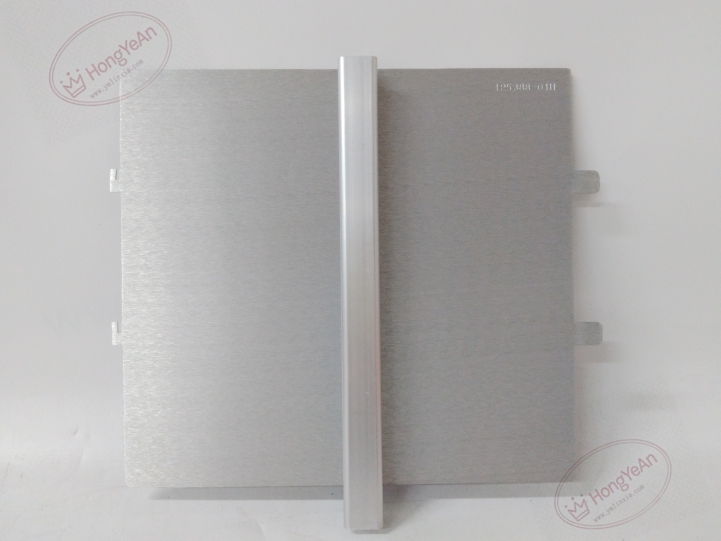
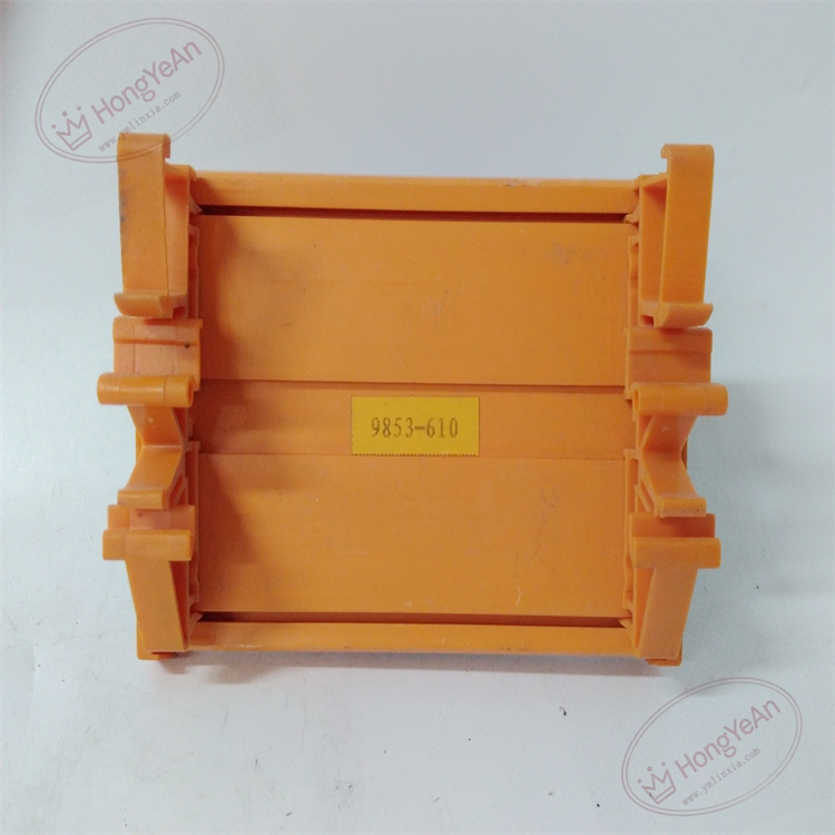
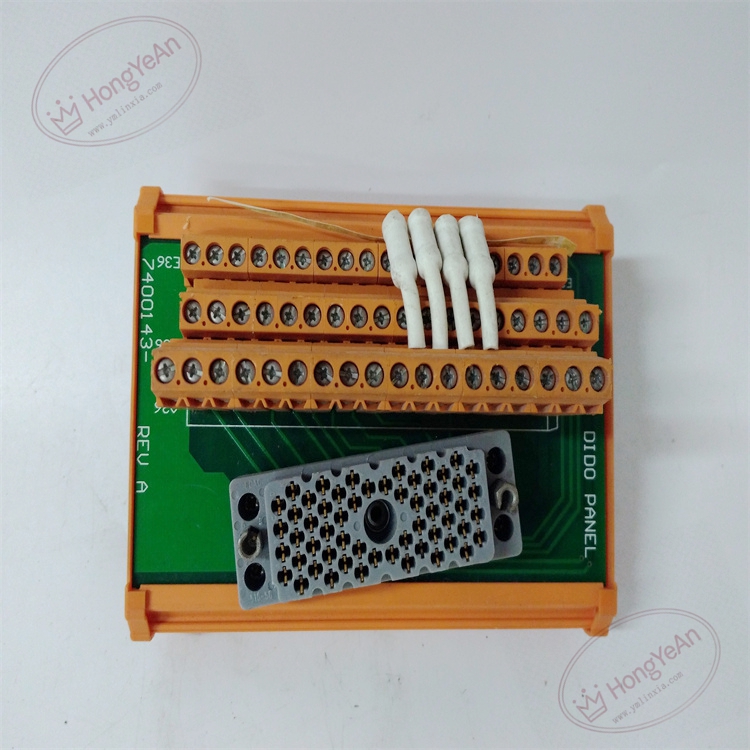
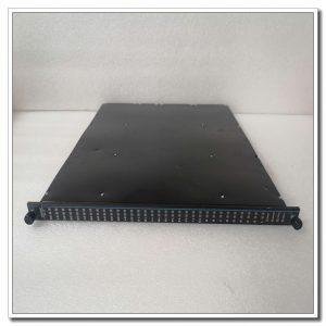
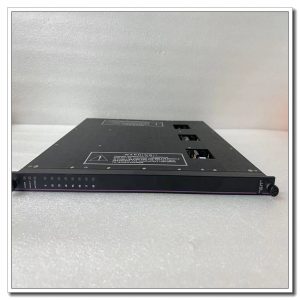
PCB assembly inside green plastic housing. Front panel fitted with multi-channel screw terminals for field valve wiring. Onboard surge suppression and current limiting circuits. One multi-pin connector for ribbon cable to link to Tricon AO module. Channel numbers are printed on panel surface.
Application Areas
This termination panel is widely deployed in petrochemical plants, refineries, gas compressor stations, thermal power plants and offshore platforms. It supports ESD emergency shutdown, burner management and turbomachinery protection systems. It transmits analog control signals from SIS AO modules to control valve positioners. Built-in protection components prevent surge or short-circuit faults on field cables from damaging the analog output module.
Maintenance Note: This is safety-related signal marshaling hardware. Fault on a single channel only affects that control loop, other analog output points remain functional. Routine maintenance should check terminal tightness and cable insulation condition.
Operation & Maintenance Suggestions
- Wear anti-static wristband before wiring modification. Cut off 24VDC instrument power supply before touching terminals to avoid surge damage.
- Keep cabinet interior clean. Dust buildup on terminals may lead to signal fluctuation. Prevent corrosive vapor and liquid from contacting PCB.
- After wiring completion, connect ribbon cable between panel and AO module. Run point-by-point signal simulation test, confirm valve responds normally and check system diagnostic logs.
- Store spare termination panels of the same model. Do not modify onboard circuit components on site; replace the whole panel once PCB suffers permanent damage.
Common Fault Handling
- Valve cannot respond to analog command: Check 4-20mA loop, terminal tightness, ribbon cable connection and positioner status.
- Signal unstable and drifting: Inspect poor shield grounding, loose terminals and electromagnetic interference.
- Overrange or low signal alarm: Check wiring polarity, cable breakage and field loop load.
- Multiple channels abnormal: Verify shared instrument power supply and common ground terminal connection.
- No output after panel replacement: Confirm panel matches AO module, inspect ribbon cable pin assignment.

Reviews
There are no reviews yet.