Description
Key Specifications
- Channel count: 8 analog input channels
- Supported signals: 4~20mA, 0~5V, 0~10V, RTD and thermocouple inputs
- Resolution: 16-bit, typical accuracy ±0.1% full scale
- Isolation: Channel-to-backplane isolation for noise suppression
- Safety rating: SIL3 compliant under IEC61508 / IEC61511
- System compatibility: Classic Tricon v9~v11 platform, hot-swappable in rack slots. Works with matched analog termination panels and dedicated ribbon cables, not compatible with Tricon CX.
- Operating environment: -40℃ ~ +70℃ operating, -40℃ ~ +85℃ storage, 5%–95% non-condensing relative humidity
- Installation notes: Channel type must be defined within SIS configuration software before commissioning. Shielded instrument wiring shall follow single-point grounding rules to reduce electromagnetic noise.
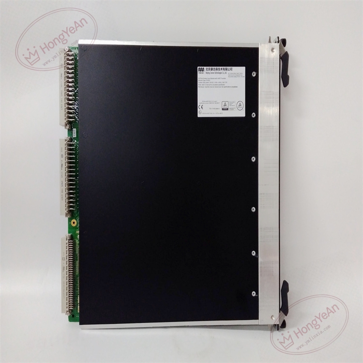
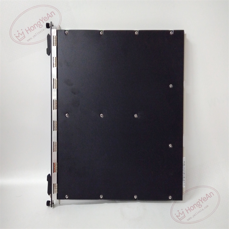
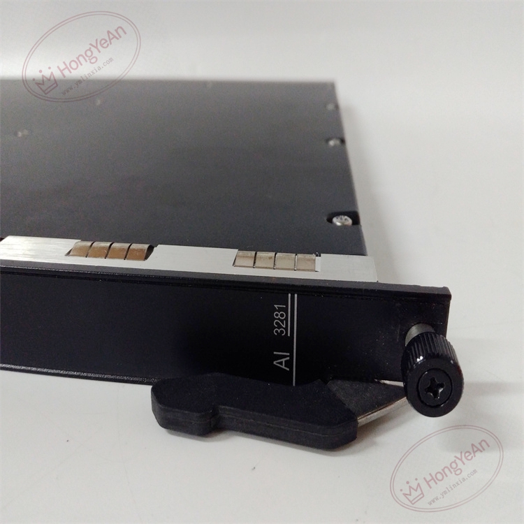
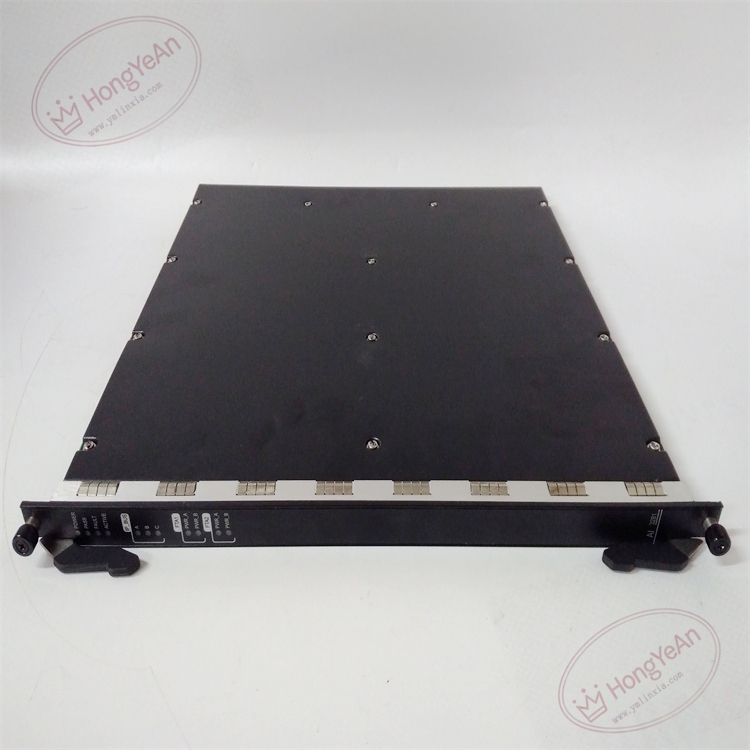
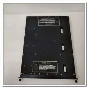
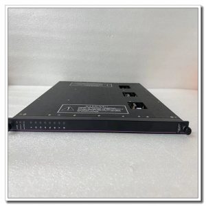
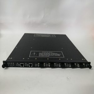
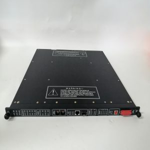
Physical Features Metal front panel fitted with multi-status LEDs for each TMR branch and per-channel diagnostic indicators. Gold-plated backplane connector for rack connection. Three independent internal acquisition circuits to implement triple modular redundancy. Part number clearly printed on card surface.
Field Application This analog input module is widely deployed in refineries, petrochemical complexes, gas compressor stations, thermal power plants and offshore platforms. It is integrated within ESD shutdown, burner management and turbine protection safety loops. It receives real-time process data from pressure, level and temperature transmitters, enabling the safety system to initiate trip actions once process variables cross preset safety limits.
Maintenance Guidelines Continuous built-in diagnostics monitor wire break, short circuit and signal overrange for each safety loop.
- Use anti-static wristband when handling the module. De-energize related field loops before card removal or insertion.
- Check LED status and system diagnostic logs during routine site inspection.
- After module replacement, perform point-by-point signal simulation test and verify measurement accuracy.
- Maintain spare modules on site. Replace the whole card upon permanent hardware failure; component-level repair on site is prohibited.
Troubleshooting Reference
- Zero or full-scale reading: Verify transmitter power supply, terminal tightness, cable continuity and wiring polarity.
- Unstable drifting readings: Check shield grounding quality, loose terminals and electromagnetic interference.
- Overrange alarm: Confirm transmitter calibration and range parameters, inspect cable short or open circuit.
- Channel error after replacement: Download correct hardware configuration and check ribbon cable pin assignment.
- Module fault LED active: Inspect rack backplane power supply and module seating, run TMR slice health diagnosis.
Reviews
There are no reviews yet.