Description
Technical Parameters
- Model: FTA-554, part number 17-550554-001
- Nominal loop voltage: 24 VDC
- Structure: Passive PCB assembly, per-channel circuit protection and screw terminal blocks
- Matching equipment: Compatible with designated Tricon I/O modules, connected by dedicated flat ribbon cable
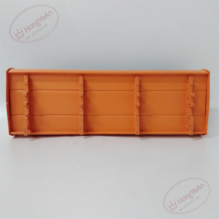
- Mounting method: DIN rail installation inside control cabinet
- Enclosure rating: IP20
- Operating temperature: -40℃ ~ +70℃
- Storage temperature: -40℃ ~ +85℃
- Humidity range: 5% to 95% relative humidity, non-condensing
- System compatibility: Classic Tricon v9~v11 TMR safety instrumented system. Incompatible with Tricon CX platform.
- Terminal specification: Screw terminals accepting solid or stranded copper wires, clearly marked channel numbers.
Physical Features
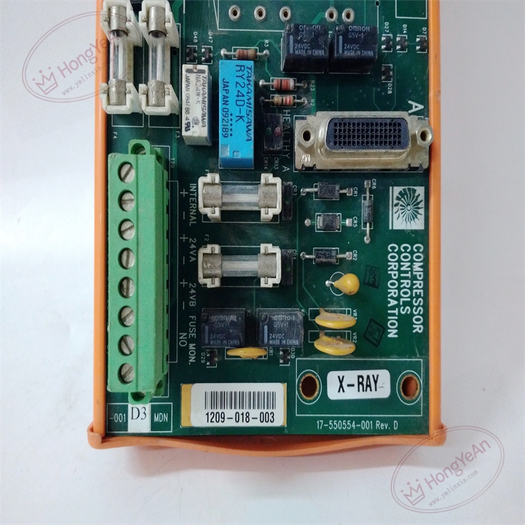
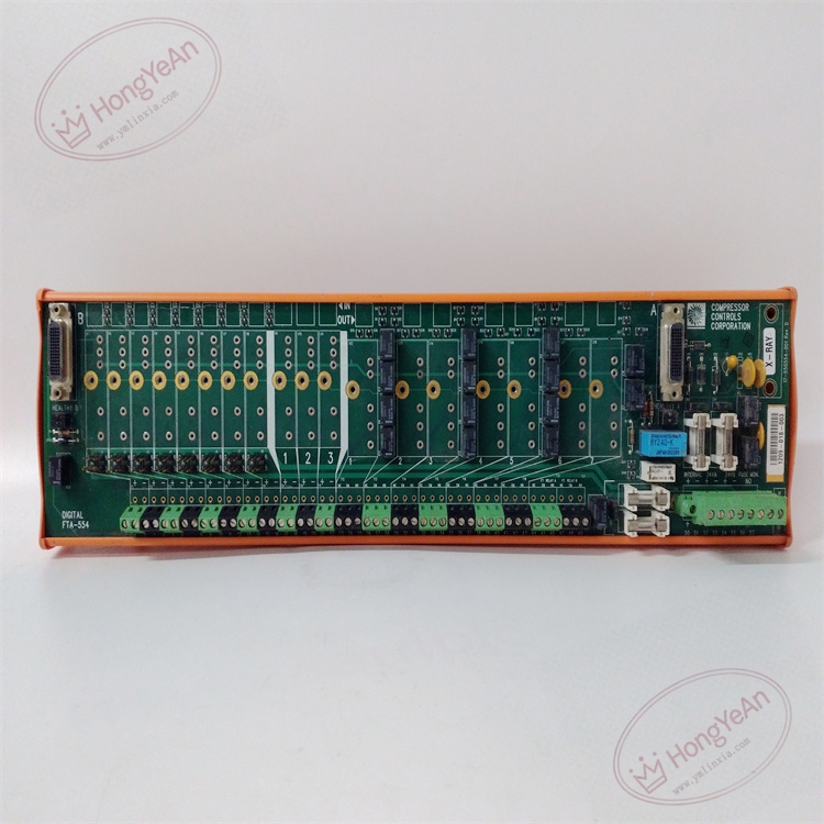
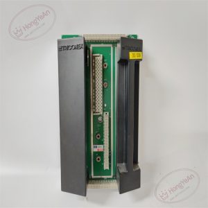
The unit is housed in green plastic casing. The front panel is arranged with multi-channel screw terminals for field instrument wiring. Onboard channel protection elements are integrated on PCB. A custom multi-pin connector is reserved for ribbon cable to link to Tricon rack I/O cards. Product part number and batch information are printed on the housing label. No processor or active logic circuits inside.
Application Context
This termination assembly is widely deployed in petrochemical plants, oil refineries, gas compressor stations, thermal power plants and offshore platforms. It supports safety instrumented loops including ESD emergency shutdown, burner management, turbomachinery protection and fire & gas systems. It routes safety signals between rack I/O cards and field actuators/transmitters. Built-in protection components can limit fault current and protect expensive Tricon I/O modules from field short-circuit and surge damage.
Maintenance & Operation Guidance
This safety-related signal marshaling hardware supports continuous channel diagnostics. Loose connectors or damaged wiring will trigger corresponding system alarms. Anti-static wristbands are required for all wiring and connector handling. Cut off the 24VDC field loop power before disconnecting terminals or ribbon cables. Maintain cabinet cleanliness. Prevent sharp metal edges from cutting cable jackets, and keep corrosive vapor and liquid away from PCB and terminal blocks. Once wiring work is completed, lock ribbon cable connectors securely. Perform point-by-point signal simulation test, verify signal stability, and check system diagnostic logs for wire break or short-circuit alerts. Keep spare FTA assemblies on site. When PCB or terminal pins suffer permanent damage, replace the whole FTA unit directly. On-site component repair or cable splicing is forbidden.
Troubleshooting Reference
- Actuator no response / no measurement reading: Check 24VDC loop power supply, terminal tightness, ribbon cable locking status and channel protection components.
- Short circuit alarm: Inspect field cable insulation failure or short circuit of solenoid coil.
- Intermittent signal jumping: Check shield grounding quality, cabinet vibration, cable compression and loose terminals.
- Missing-load alarm for unused channels: Install required load resistors on idle output loops.
- System fault after FTA replacement: Confirm the FTA matches the I/O module model, verify ribbon cable pin assignment.
Reviews
There are no reviews yet.