Description
Full Technical Details
- Complete part identifier: T8800C, PD8800, PCB130100 (PCB drawing number)
- Supply voltage: 24 VDC, operating range 16–30 VDC
- Channel design: Multiple discrete signal channels with built-in per-channel protection circuits including fuses and surge suppression components
- Safety certification: IEC61508 SIL3, UL, CE and ATEX approvals for hazardous area projects
- Mechanical mounting: Standard DIN rail installation inside control cabinets
- Enclosure protection: IP20, only for indoor cabinet use, not for direct field exposure
- Supported system: ICS Triplex T8800 TMR safety platform. Matches the corresponding T8800 series I/O modules and factory prefabricated ribbon cables
- Temperature limits: Operating -40℃ ~ +70℃; storage -40℃ ~ +85℃
- Humidity: 5%–95% RH, non-condensing
- Terminal type: Screw terminals, compatible with solid or stranded copper wires. Clear channel number marking on PCB surface
- Built-in diagnostics support: Supports wire break and short-circuit diagnostics fed back to the TMR controller
- Installation guidelines: Separate signal wiring from high-power AC cables. Shielded instrument cable must be adopted for field wiring, and single-point grounding must be implemented following project specifications. Avoid pinching, sharp bends and mechanical tension on ribbon cables. Do not modify or remove the onboard protection components on site.
Hardware Description
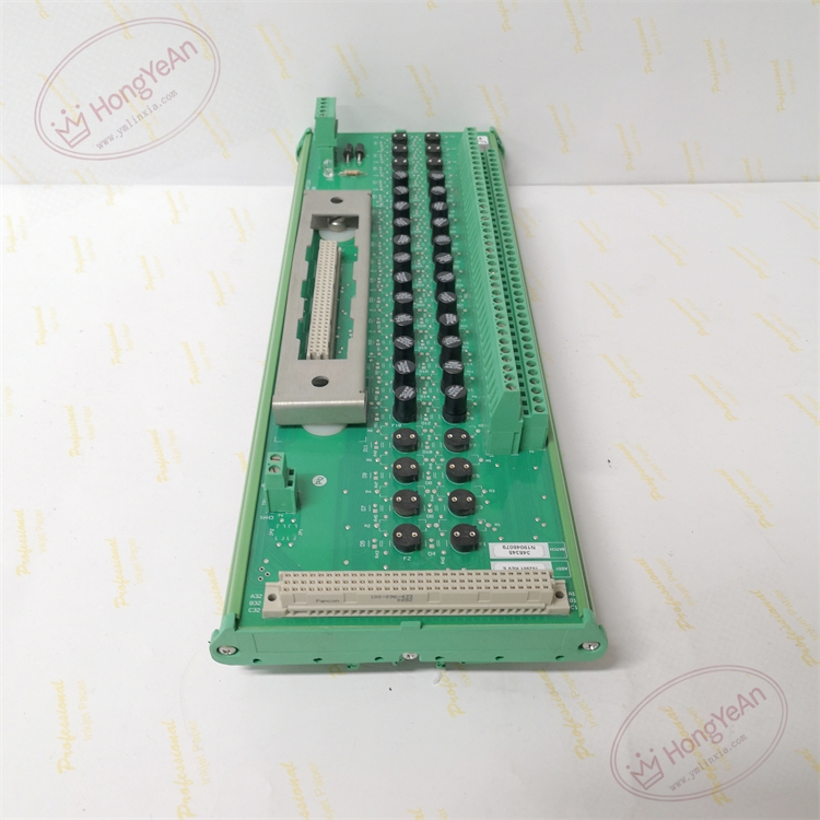
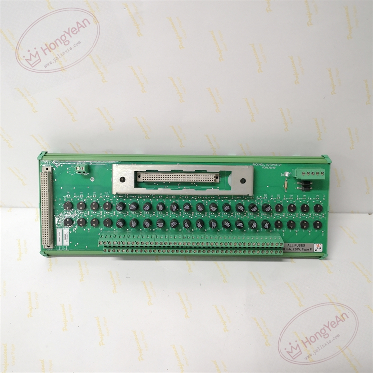
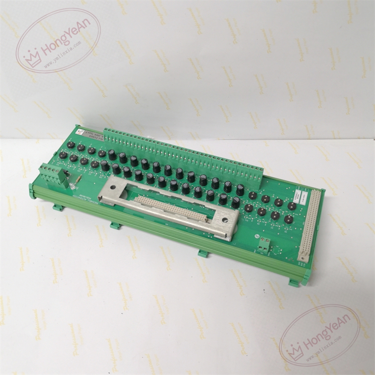
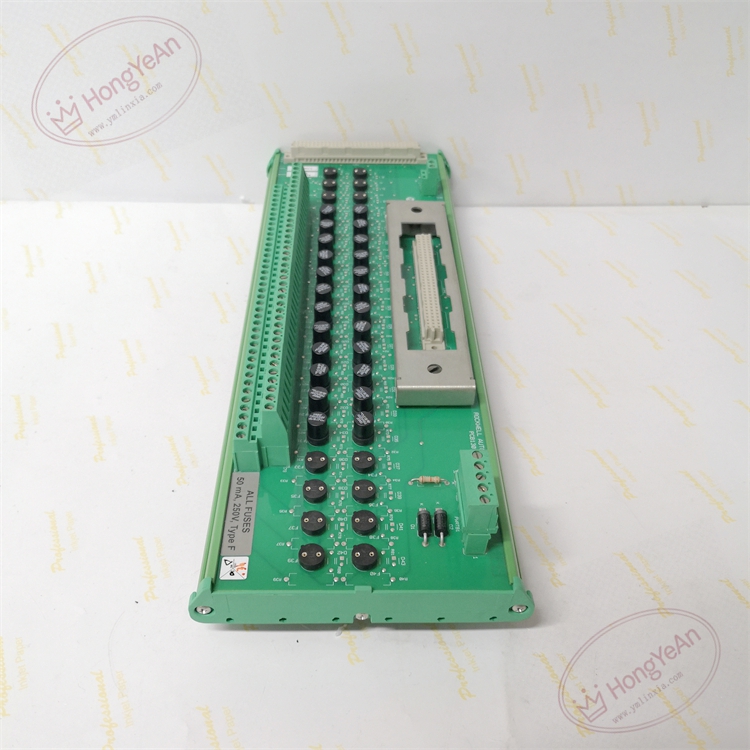
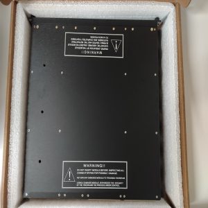
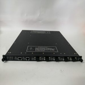
Green printed circuit board assembly with plastic DIN rail housing. Front layout consists of rows of screw terminals and small status indicator LEDs for each channel. A custom multi-pin edge connector is fitted for factory ribbon cable connection to rack I/O cards. The PCB is marked with drawing number PCB130100 and part code PD8800. It is a passive field termination unit with no on-board microprocessor.
Deployment Scenarios
This FTA assembly is widely adopted in petrochemical facilities, oil refineries, gas compressor packages, thermal power stations and offshore platforms. It serves safety instrumented loops for ESD emergency shutdown, burner management, turbomachinery protection and fire & gas detection systems. It routes discrete trip and alarm signals between T8800 rack I/O cards and field solenoid valves, proximity switches and flame detectors. The integrated fuses and surge devices limit fault energy and prevent back-end damage to expensive rack I/O modules during field wiring short-circuit or surge events.
Maintenance Guidance
This safety-related marshaling hardware continuously participates in SIS loop diagnostics. Loose terminals, blown fuses or damaged cable pins will trigger channel alarms in the engineering workstation. All disconnection work must use anti-static wristbands, and the related 24V field loop power should be isolated before removing the ribbon cable or loosening terminal screws. Regular inspection should verify LED status, terminal tightness, cable sheath integrity and cable routing protection. Dust accumulation inside the cabinet should be cleaned periodically to prevent leakage current across PCB traces. After wiring replacement or FTA swap, perform point-by-point signal simulation test for every channel, and confirm no diagnostic alarms in the system software. Spare FTA assemblies and spare fuses should be kept on site. If PCB traces, terminals or protection circuits are permanently damaged, replace the whole FTA unit. On-site component-level repair or cable splicing is prohibited.
Troubleshooting Reference
- Entire bank of channels no signal: Inspect ribbon connector lock status, check for blown common fuse, verify 24VDC field power supply.
- Single channel failure: Usually caused by blown channel fuse, broken field wire, bent connector pin or loose terminal screw.
- Intermittent signal loss: Check cabinet vibration, loose terminals, shield grounding failure, cable compression and abrasion.
- False wire break diagnostic alarm: Verify loop load resistance, check for high resistance at terminal connections.
- Fault alert after FTA replacement: Confirm compatibility with matched I/O module and ribbon cable, double check pin assignment and wiring polarity.
-300x300.jpg)
Reviews
There are no reviews yet.