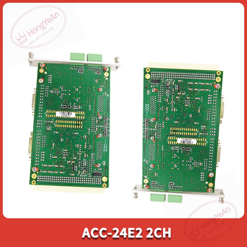
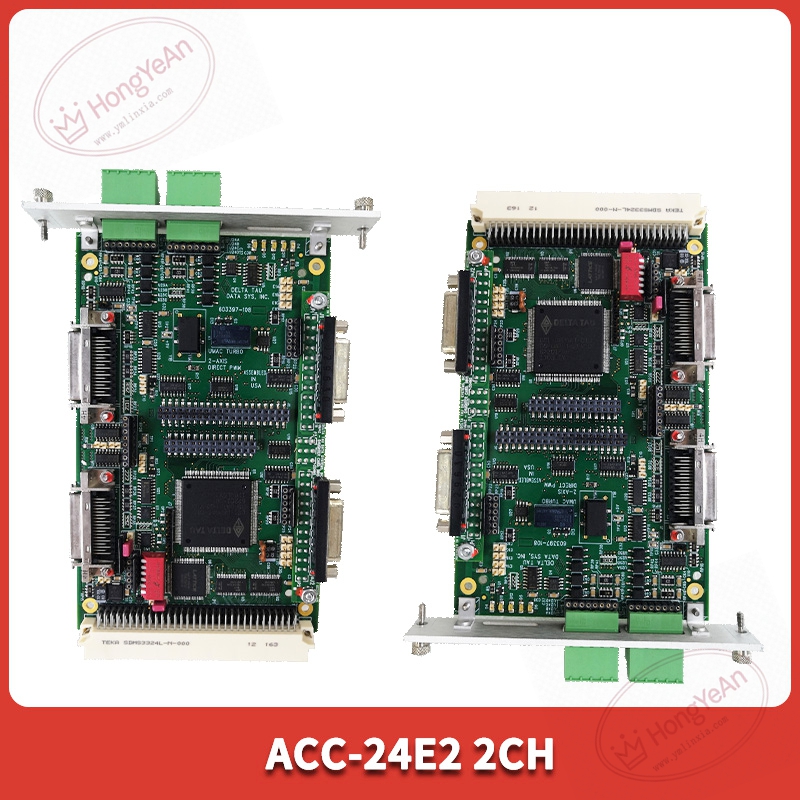
Description
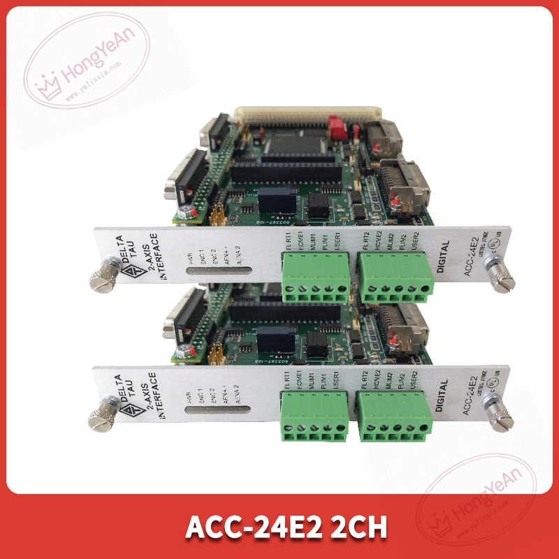
Core performance features
This board adopts internal slot installation mode inside drive cabinet, powered by drive backplane without extra external power wiring. Dual‑channel encoder input can connect two sets of incremental encoder sensors at the same time. It processes A/B/Z phase differential pulse signals, completes signal filtering and level conversion, transmits calculated speed and position value to main control hardware. Status LED lamps show power‑on state, signal loss and channel error alarm. Built‑in signal diagnosis function can identify open‑circuit, short‑circuit and abnormal pulse frequency of encoder loop. Supports configuration of counting multiplier, pulse resolution and monitoring threshold through drive software. Horizontal installation operating temperature 0‑55℃, IP20 grade, only for cabinet‑inner deployment. Some variants have conformal coating for dusty workshop environments.
On‑site application scenarios
Widely matched with large‑size servo and main drive equipment in metallurgy, papermaking and lifting machinery. Dual‑channel design can realize main‑standby encoder redundant acquisition or collect position signals of two independent moving shafts. When original feedback interface fails on‑site, replacing ACC‑24E2‑2CH can restore closed‑loop control. No need to change encoder field wiring, just adjust software channel parameters according to actual encoder specification. It belongs to conventional maintenance spare parts for high‑precision speed‑regulating occasions. Stable pulse acquisition helps avoid speed jitter and position drift caused by feedback signal distortion.
Installation & operating notes
Cut off drive main power and auxiliary power before plug‑in and pull‑out. Live hot‑plugging is forbidden to prevent chip damage caused by surge and static electricity. Encoder signal cable must use shielded twisted‑pair, keep laying distance away from high‑power cables to suppress electromagnetic interference. Wrong phase sequence will cause speed feedback reversal and mechanical oscillation. Backup drive parameter files before replacement. After installing new board, set pulse resolution and counting mode according to encoder nameplate, and carry out no‑load commissioning test. Keep cabinet ventilation unobstructed. Excessive temperature will increase signal acquisition error. Do not disassemble board components on‑site; replace whole unit if permanent hardware fault occurs.
Common field phenomena & disposal thoughts
- Drive reports encoder feedback fault: Check field cable shielding and wiring integrity. Re‑seat interface board. Confirm software parameter matches actual encoder. If external circuit is normal, board hardware failure may exist.
- Motor speed jitter in operation: Check shielding grounding status. Optimize filter parameters inside drive software. Eliminate surrounding interference sources. Test with spare board for comparison.
- One channel no feedback signal: Inspect wiring of corresponding channel. Confirm channel function is enabled in parameters. Check whether encoder sensor itself is damaged.
- Intermittent position deviation: Check cabinet temperature and connector contact condition. Clean dust and oxide on connectors. Rule out mechanical wear of encoder body.
Reviews
There are no reviews yet.