Description
Core performance features
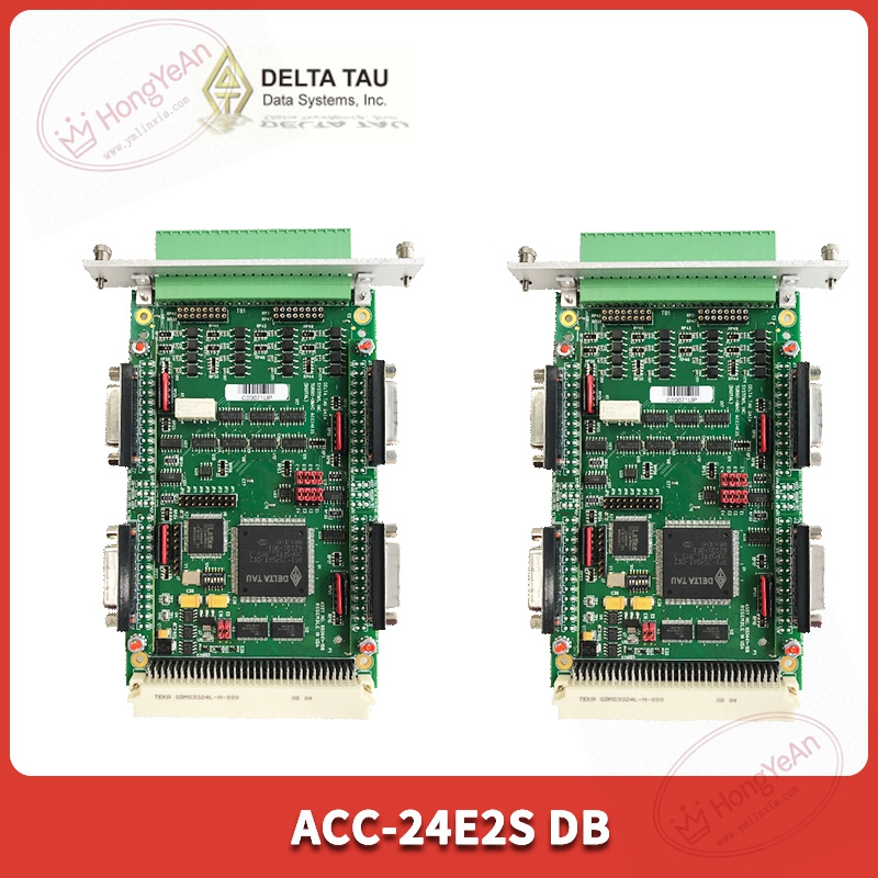
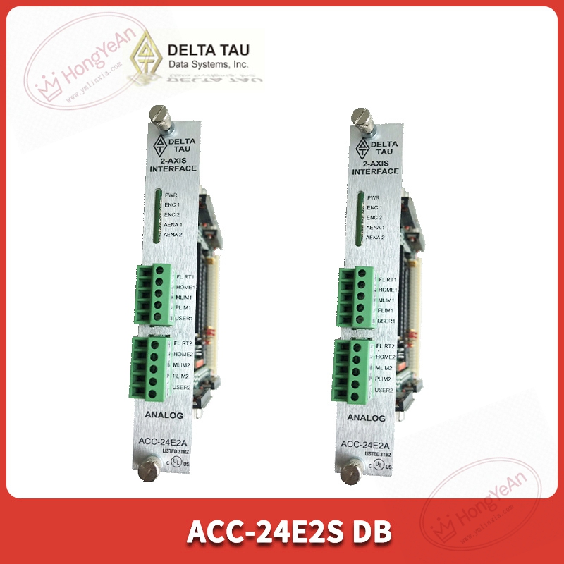
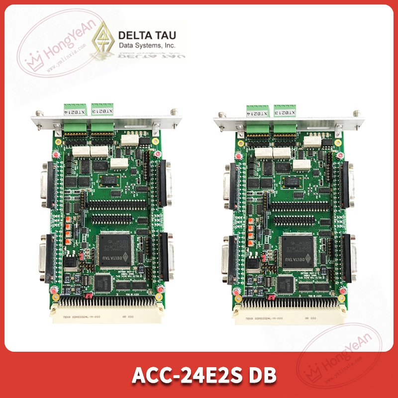
This board plugs into the UMAC rack and gets power from the backplane bus. It provides four groups of motion channels, supporting ±10V analog servo output as well as pulse‑direction signal for stepper drives. Accepts differential incremental encoder A/B/Z feedback signals. Built‑in channel diagnostics can detect signal loss, short‑circuit and abnormal pulse frequency. Front‑panel LED indicators show power status, channel activity and internal faults. DB version uses DB‑series connectors for field wiring, different from terminal‑block type ACC‑24E2S‑TB. Jumper settings allow users to select differential or single‑ended encoder signal mode. Works with PMAC programming environment, each axis can configure gain, limit and homing parameters separately. Operating temperature 0‑60℃, IP20 protection, cabinet‑mount only. Original manufacturer has ended production, mostly circulated as maintenance spare parts.
On‑site application scenarios
Applied in multi‑axis automation devices, precision assembly equipment and special‑machine motion control cabinets. It expands axis quantity for UMAC controllers without replacing main CPU hardware. When axis feedback or output channel fails, technicians can replace only this expansion board. No need to modify mechanical structure, just verify jumper settings and download existing motion parameters. Common spare stock for old Delta Tau motion systems. After replacement, perform no‑load jog test to check encoder counting and servo output response before formal operation.
Installation & operating notes
Power off rack power supply before pulling out or inserting the board. Hot‑swap is not supported. DB‑connector cables should adopt shielded wiring, separate from high‑power cables to reduce interference. Wrong jumper setting for encoder signal will cause position counting error or axis oscillation. Save project parameters before hardware swap. After installing new board, confirm jumper configuration matches actual encoder hardware. Complete simulation test for each motion channel. Keep cabinet ventilation good. Dust and oxidation on connectors will trigger intermittent position drift. Do not disassemble board housing on‑site; replace whole unit upon permanent hardware damage.
Common field phenomena & disposal thoughts
- Board indicator does not light after power‑on: Check rack backplane power supply. Re‑seat board in slot. If power input is normal, internal hardware damage may exist.
- Encoder position counting abnormal: Inspect DB connector fastening status. Check jumper for differential / single‑ended mode. Verify encoder power supply and cable shielding grounding.
- Axis no response to motion command: Check servo‑output wiring definition. Confirm axis enable state and limit‑parameter settings in PMAC software.
- Axis oscillates during movement: Adjust servo gain and dead‑zone parameters. Eliminate nearby electromagnetic interference sources. Check mechanical jamming of actuators.
Reviews
There are no reviews yet.