.jpg "艾默生-1C31169G02-(1)")
.jpg "艾默生-1C31169G02-(2)")
Description
Technical highlights
Two independent DB9 serial ports, configurable baud‑rate from 300‑19200bps, supports multiple common serial communication protocols. Provides channel‑level diagnosis, can report communication timeout, frame error alarm to DCS operator station. Supports hot‑swap operation, power supplied from Ovation rack backplane. Typical power consumption 3W, maximum 4W. Operating ambient: 0℃ ~ +60℃; storage‑40℃ ~ +85℃; humidity 5‑95% non‑condensing; IP20 cabinet‑mount only. Compatibility note: Must match Ovation DPU firmware version. After replacement, download serial communication configuration file; wrong parameter setting will result in external device communication failure. It cannot be interchanged with highway link controller 1C31166G02.
.jpg)
Physical features
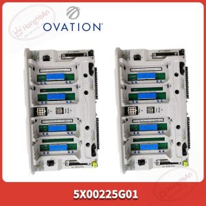
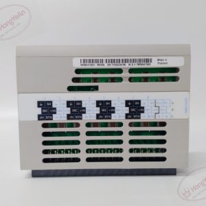
Standard Ovation single‑slot plug‑in electronic module. Front panel fitted with two DB9‑D‑sub serial connectors, multi‑group LED indicators for module run, fault and serial‑port status. Rear high‑density gold‑plated connector connects to rack backplane for power and internal bus signal transmission. Part‑number 1C31169G02 is marked on module nameplate. PCB adopts conformal‑coated treatment for dust‑proof and anti‑corrosion performance in thermal‑power cabinet surroundings.
Site application scenario
Mainly deployed in thermal‑power Ovation DCS cabinets. Responsible for data interaction between DCS and serial‑access devices such as flue‑gas analyzers, vibration monitoring instruments and third‑party auxiliary controllers. Module failure will cut off all serial‑port data transmission, related external instrument points lose upload function. Hot‑swap replacement is allowed under normal system running condition. After replacement, insert module into target rack slot, check DB9 serial‑cable connection, download serial‑communication configuration, verify data receiving‑transmitting status and point value validity before commissioning.
Installation & maintenance notes
Take anti‑static measures during module handling. Avoid scratching rear backplane connector pins. Serial signal cables adopt shielded twisted‑pair, separate from high‑power cables to reduce electromagnetic interference. Pay attention to RS485 bus terminal‑resistor setting. Backup serial‑communication configuration archive before hardware swap. Check DB9 connector terminals for oxidation and looseness during routine overhaul. On‑site component‑level repair is prohibited, replace complete module under permanent hardware damage.
Common site fault performances
- Serial‑port cannot receive data: Check baud‑rate, parity‑bit configuration consistency, inspect cable wiring and terminal‑resistor setting.
- Module communication fault LED lights up: Re‑download valid configuration file, check backplane contact quality.
- Intermittent data loss: Examine cable shielding grounding, cabinet temperature and dust accumulation.
- Two serial‑ports no response: Verify rack backplane power supply and DCS hardware database configuration.
-300x300.jpg)
-300x300.jpg)
Reviews
There are no reviews yet.