Description
Hardware & Electrical Specifications
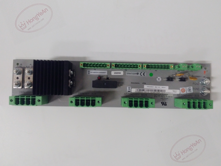
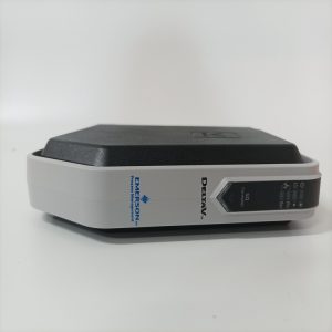
‑ Manufacturer: Emerson (Westinghouse legacy) ‑ Compatible System: Ovation DCS distributed control system ‑ Input: 22‑28 VDC primary power input ‑ Output: Multiple independent 24 VDC output branches, individual electronic over‑current protection per channel ‑ Protection: Per‑channel electronic circuit‑breaker, undervoltage monitoring, short‑circuit fold‑back protection ‑ Fault Reporting: Dry‑contact alarm relay, status LED indicators for channel fault and power‑good condition ‑ Connectors: High‑current screw terminal blocks for main power input and distributed output branches ‑ Mounting: Standard Ovation rack‑mount installation ‑ PCB Finish: Conformal coated for harsh plant environments (ISA‑S71.04 G3) ‑ Hot‑swap: Hot‑swappable with properly redundant power setup
Environmental Specifications
‑ Operating Temperature: ‑40 °C ~ +70 °C, output derating at high ambient temperature ‑ Storage Temperature: ‑40 °C ~ +85 °C ‑ Relative Humidity: 5%‑95 % non‑condensing ‑ Vibration & Shock: Designed for power‑plant cabinet EMI and transient conditions
Mechanical Data
‑ Weight: approx 2.0 kg ‑ Form‑factor: Ovation standard rack‑mount module
Core Functions
- Multi‑branch power distribution: Distributes 24 VDC power to Ovation controllers, I/O modules and field instrument loops.
- Per‑channel over‑current protection: Independent electronic circuit breakers isolate short‑circuited output branches without collapsing the whole system power rail.
- Power‑fault diagnostics: Visual LED status plus relay alarm contact report loss of input power or channel overload faults to DCS.
- Redundancy coordination: Works in diode‑auctioneered redundant power architectures to enhance system availability.
- Load isolation: Faulty downstream branch is cut off automatically to protect remaining healthy DCS loads.
Installation, Replacement & Critical Warnings
- For single‑feed non‑redundant cabinet, de‑energize upstream 24 VDC source before replacement; hot‑swap only permitted under redundant power configuration.
- Verify main input voltage is within 22‑28 VDC range; overvoltage will damage internal distribution circuits.
- Torque all high‑current screw terminals to specified torque value; loose terminals result in overheating and intermittent power dropout.
- After installation, confirm power‑good LED is illuminated, verify each output‑branch voltage and test alarm‑relay function.
-
Common failure mode: Over‑current damage to individual output channels, surge from field wiring. Investigate field‑side short‑circuit events when channel‑fault alarms trigger.
Reviews
There are no reviews yet.