Description
Technical highlights
Supports PROFIBUS‑DP V0 / DPV1 protocol, maximum 125 slave nodes, baud‑rate range 9.6 kbit/s‑12 Mbit/s. Backplane power consumption: 800 mA @5VDC, 3 mA @24VDC. Equipped with D‑sub PROFIBUS‑DP interface and RS232 configuration debugging port. Module configuration is completed via ProSoft Configuration Builder (PCB) software. Data interaction with ControlLogix controller relies on backplane ladder logic program. Operating ambient: 0℃ ~ +60℃; storage‑40℃ ~ +85℃; humidity 5‑95% non‑condensing; IP20 cabinet‑mount onlyProSoft Te…. Compatibility note: Installs in standard 1756 rack slot. Controller firmware version needs to meet minimum requirement. Incorrect configuration file will trigger bus communication breakdown.
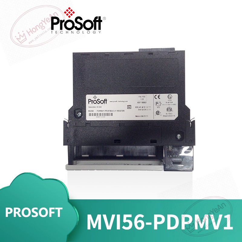
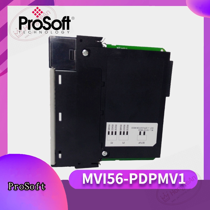
Physical features
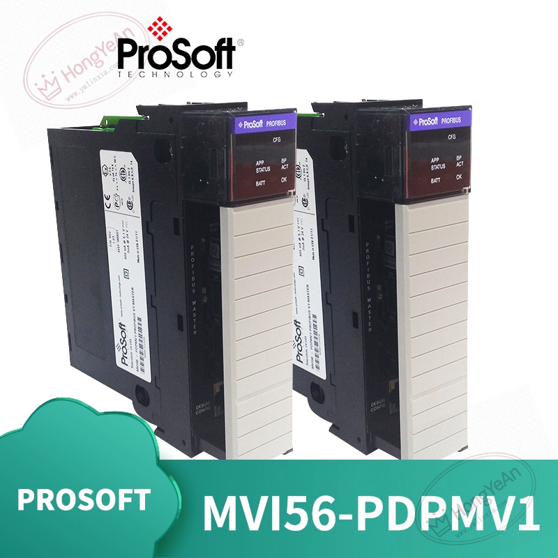
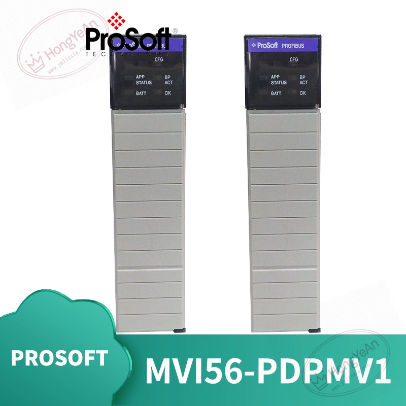
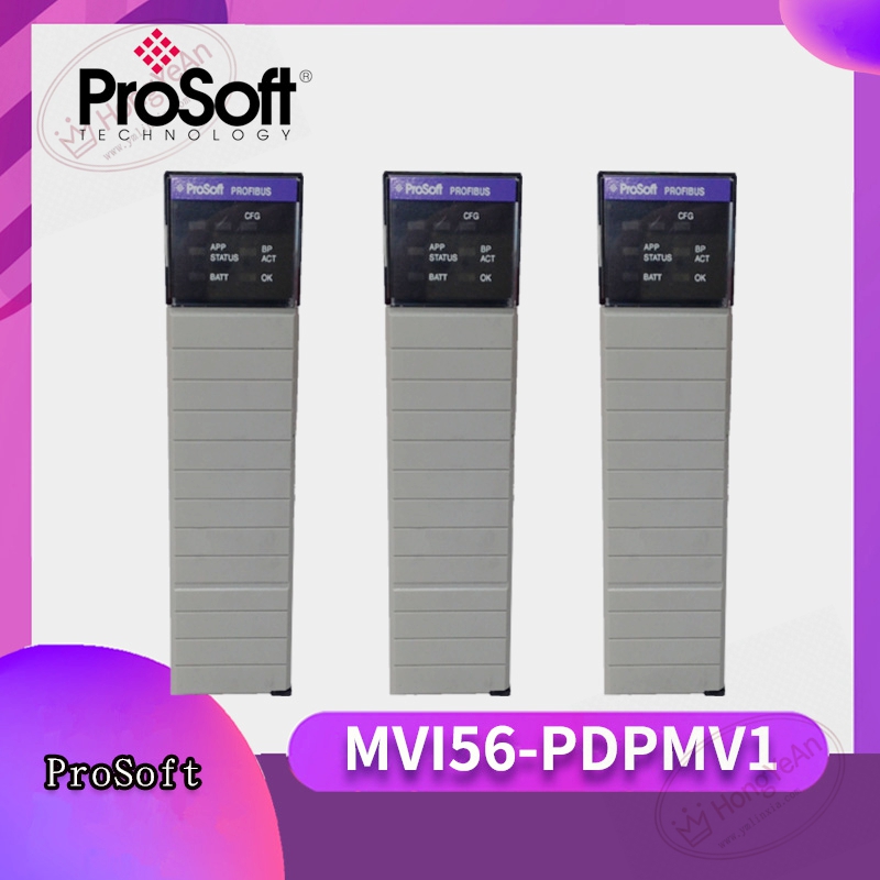
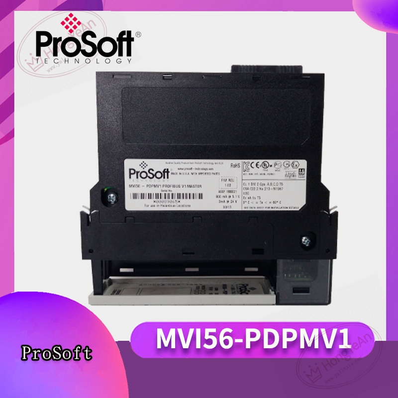
Standard 1756 single‑slot plug‑in module. Front panel integrates multi‑group LED status indicators for module health, backplane communication, application and bus fault. D‑Sub 9‑pin female connector for PROFIBUS‑DP field wiring. Rear gold‑plated connector docks to ControlLogix rack backplane for power and internal bus transmissionProSoft Te…. Part‑number MVI56‑PDPMV1 is printed on module nameplate. PCB adopts conformal‑coated treatment for dust‑proof performance in factory cabinet surroundings.
Site application scenario
Commonly deployed in manufacturing, chemical and power‑plant ControlLogix automation racks. It connects ControlLogix system to PROFIBUS‑DP slaves including variable‑frequency drives, remote I/O modules and valve terminals. Module failure will cut off whole PROFIBUS‑DP segment communication, all slave devices lose data interaction. After replacement, insert module into target rack slot, complete hardware recognition within ControlLogix project, download matching PCB configuration file, set PROFIBUS baud‑rate and slave list, verify each slave online status before commissioning.
Installation & maintenance notes
Power off rack before module swap, anti‑static protection is mandatory during handling. Avoid scratching rear backplane connector pins. Use standard shielded PROFIBUS‑DP cable. Termination resistors shall be fitted at both ends of bus segment. Keep fieldbus cables separated from high‑power cables to restrain electromagnetic interference. Backup configuration file and ControlLogix ladder logic before hardware replacement. On‑site component‑level repair is prohibited; replace complete module under permanent hardware damage.
Common site fault performances
- Partial or all PROFIBUS slaves offline: Check bus cable and termination resistor, verify baud‑rate setting and slave list configuration.
- Module application fault LED illuminates: Re‑download valid PCB configuration, check backplane contact quality.
- Intermittent slave drop‑out: Inspect cable shielding grounding, cabinet temperature and dust accumulation.
- Data cannot exchange between module and ControlLogix CPU: Check ladder logic program and backplane communication status.
Reviews
There are no reviews yet.