Description
Technical highlights
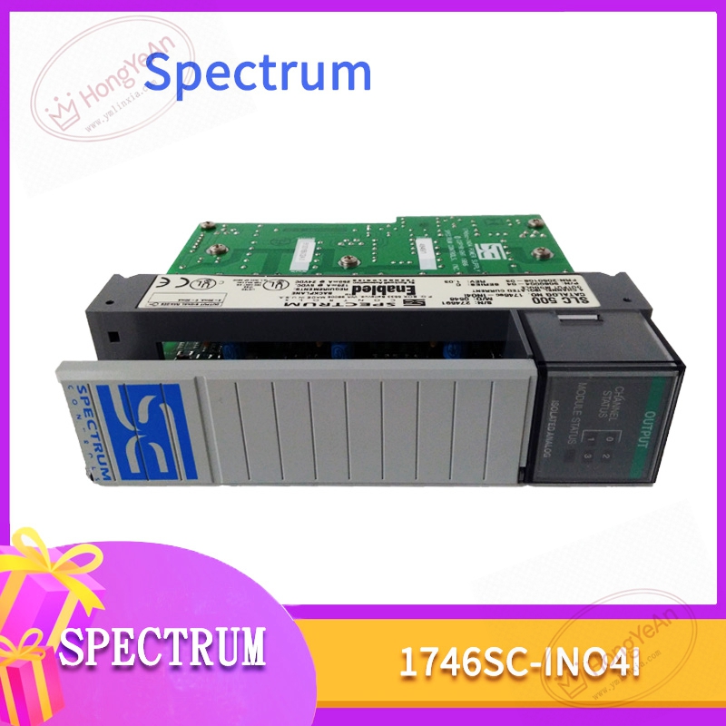
4 fully isolated current output channels, signal range 0‑20mA / 4‑20mA / 0‑21mA, 16‑bit resolution, basic accuracy ±0.08% FS at 25℃. 500VAC isolation between field side and backplane, also channel‑to‑channel isolation. Supports output clamping, ramp function and fail‑safe state configuration. Power supply: 120mA@5VDC from SLC500 backplane, optional external 24VDC auxiliary power. Max power dissipation 5W. Operating ambient: 0℃ ~ +60℃; storage‑40℃ ~ +85℃; humidity 5‑95% non‑condensing; IP20 cabinet‑mount only. Compatibility note: Fits standard 1746 SLC500 rack slot. Configure module ID code within RSLogix500 software. Cannot be mixed with ordinary 1746‑NO4I non‑isolated module parameter files.
Physical features
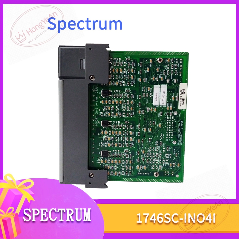
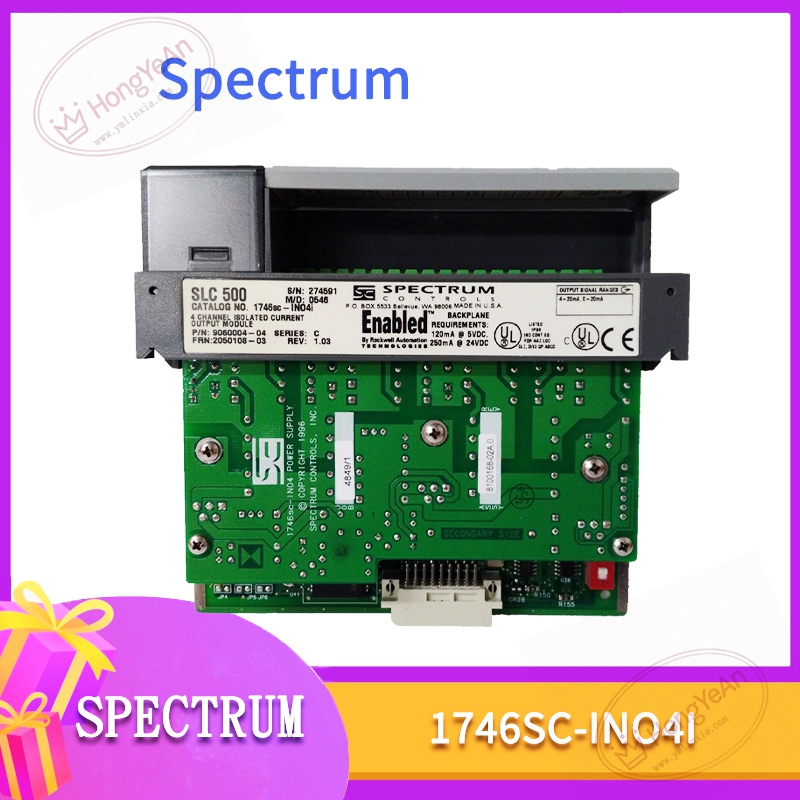
Standard SLC500 single‑slot plug‑in hardware. Front panel has multi‑channel status LED indicators and removable field‑wiring terminal block. Rear gold‑plated connector connects to SLC500 rack backplane for power and backplane data exchange. Part‑number 1746SC‑INO4I is printed on module housing label. PCB uses conformal‑coated treatment for dust‑proof and anti‑corrosion performance in factory cabinet surroundings.
Site application scenario
Mainly deployed in manufacturing and small‑process‑industry SLC500 PLC cabinets. It outputs analog current set‑point signals to control valves, dampers and field actuators for closed‑loop adjustment. Single‑channel damage will make corresponding control loop invalid. Whole‑module fault causes loss of all four AO channels. After replacement, insert into assigned rack slot, fasten wiring terminal block, set module ID code in RSLogix500 project, download hardware configuration, test each channel output amplitude and stability before commissioning.
Installation & maintenance notes
Power off rack before module replacement, anti‑static protection is required during handling. Avoid scratching rear backplane connector pins. Analog signal cables adopt shielded twisted‑pair, keep separated from high‑power cables to reduce electromagnetic interference. Check terminal block oxidation and looseness during routine overhaul; poor contact will cause signal drift. On‑site component‑level repair is prohibited. Replace complete module when permanent hardware damage occurs.
Common site fault performances
- Individual channel no output or output offset: Check field load resistance and terminal wiring condition.
- Module reports channel fault alarm: Verify output clamping parameter, inspect field short‑circuit risk.
- All channels no response: Check backplane power supply and module ID code configuration.
- Intermittent signal jitter: Inspect cable shielding grounding and cabinet heat‑dissipation condition.
Reviews
There are no reviews yet.