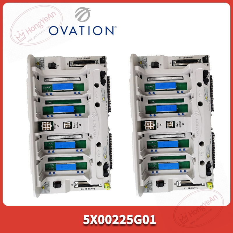
Description
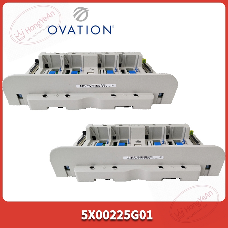
Technical highlights
Designed for OCR1100 controller electronic unit. Power input 24 VDC ±10%, maximum power consumption 40 W. Supports two groups of I/O module combinations (electronic module plus personality base). Low‑impedance grounding design improves anti‑interference performance. No independent processing function; operation must cooperate with matched controller electronic board. Operating ambient:‑20℃ ~ +70℃; storage‑40℃ ~ +85℃; humidity 5‑95% non‑condensing; IP20 cabinet‑mount only. Compatibility note: Only matches OCR1100 series controller hardware. After replacement, verify backplane bus connection and system hardware database configuration. Mismatched controller variant will trigger hardware diagnostic alarm.
Physical features
Rack‑mount base assembly. Front side is equipped with status LED indicators and locking latches. Internal P1/P2 backplane connectors implement power supply and high‑speed internal bus signal transmission. Multiple slot positions are reserved for controller and I/O module installation. Part‑number 5X00225G01 is marked on housing nameplate. PCB adopts conformal‑coated treatment for dust‑proof and anti‑corrosion in power‑plant cabinet surroundings.
Site application scenario
Mainly deployed in thermal‑power Ovation DCS control cabinets. It acts as carrier for DPU controller and local I/O modules, realizing bus signal routing and power distribution. Base assembly failure will cause controller startup failure and loss of local I/O channels. Under redundant DPU configuration, standby controller will take over to avoid process shutdown. After replacement, install corresponding controller electronic card and I/O modules, check backplane connector locking status, verify DPU online status and I/O point reading before commissioning.
Installation & maintenance notes
Power off rack before base replacement. Anti‑static protection is required during handling. Avoid pin deformation of internal backplane connectors. Separate field signal cables from high‑power cables to reduce electromagnetic interference. Check connector tightness during routine overhaul; dust and oxidation will lead to intermittent communication faults. On‑site component‑level repair is prohibited. Replace complete base assembly under permanent hardware damage.
Common site fault performances
- Controller cannot power‑on, status LED keeps off: Check 24 VDC input power and base internal fuse.
- DPU reports hardware mismatch alarm: Confirm matching with OCR1100 controller electronic board, verify DCS hardware database configuration.
- Intermittent I/O communication error: Inspect backplane connector contact condition, cabinet temperature and dust accumulation.
-
Local I/O modules unrecognized by system: Re‑check module slot installation and backplane bus integrity.
-300x300.jpg)
Reviews
There are no reviews yet.